Start with a real-life situation
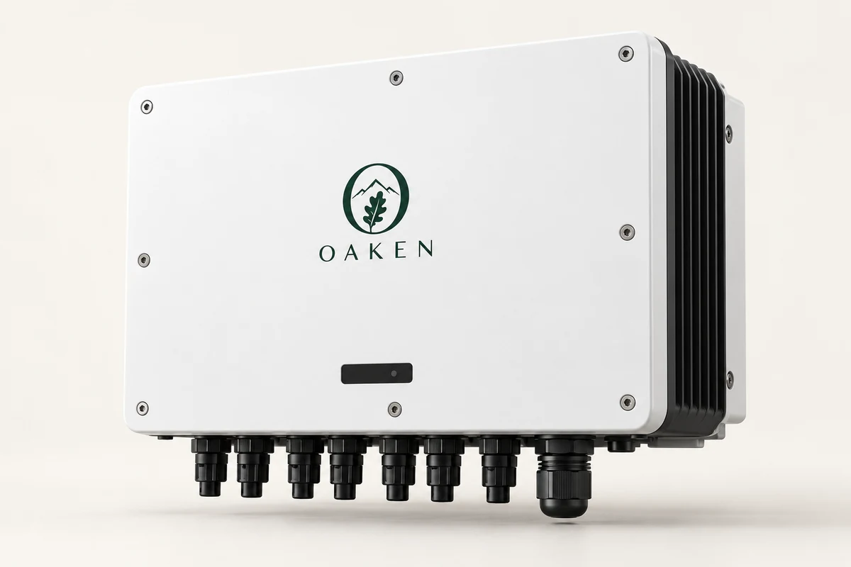
The inverter is switched off, but illuminated modules can still create DC voltage. An “off” display does not mean every cable is de-energized. That is why drawings, labels and safe isolation procedures matter.

1. DC, AC and the point of connection
Array, inverter input, AC output, switchboard and point of connection have different limits. The single-line diagram should identify energy paths and disconnects. Fuse, switch, cable and surge-protection choices depend on ratings, environment and manufacturer instructions.
2. Grid outage and backup isolation
A grid-connected inverter must not unintentionally energize a failed grid. Backup needs a verified independent path, transfer arrangement and control logic. Switching one device off or changing settings is not a substitute for safe isolation and professional testing.
3. Evidence to request at handover
Request as-built drawings, equipment/settings list, warning labels and agreed test records. Protection evidence must match the delivered model and version. Operator training should identify emergency isolation locations and response owners.
4. Signals to stop and seek review
Do not dismiss burning smell, damaged cables/connectors, water ingress or repeated protection trips. Keep the area safe and contact qualified responders under the site plan. Users should not open enclosures, reconnect circuits or bypass protection.
Check before deciding
- Single-line diagram and emergency isolation
- Exact protection models and test records
- Maintenance owner and response plan
CHECK YOUR UNDERSTANDING
A quick knowledge check
Sources & scope
- U.S. DOE SETO · A Guide to Fire Safety with Solar Systems
- U.S. DOE FEMP · Install and Commission a Photovoltaic System
Named technical review has not yet been recorded.
Preliminary guidance. Structural, safety and construction approval requires the responsible engineer and final model documents.